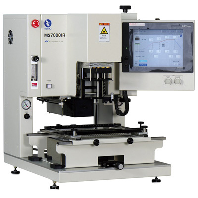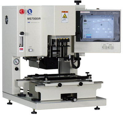
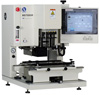
MS7000IR
MS7000IR is the automatic heating rework system.
It is controlled by ITTS (Intelligence Thermal Trace System) . The
top heater is by the high response middle-range infrared rays (MIR),
and the bottom heater is Far IR. Each heater are controlled by ITTS.
Therefore, the auto-thermo profile creation function arranged the
upper and lower side of the board.
-
ITTS auto-thermo-trace system controls upper and bottom
heating individually.
-
Creation of the optimal temperature profile is
automated.
-
The nozzle change is un-necessary.
-
Top heater is the high response Middle infrared rays.
-
Z axis is motor controlled, and it is semi-auto system.
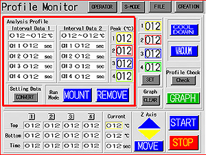
ITTS Operation


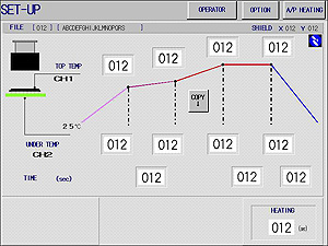
ITTS setup screen
MS7000IR is a rework machine with a
auto-thermo trace system. The temperature sensor for ITTS is two
managing locations. They are the surface of the reverse-side of the
board, and other one is the surface of the package. Those sensor must be
able to detect surface temperature precisely.
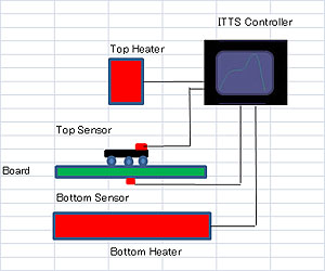
ITTS Diagram
The required temperature profile data is input to the
four windows, MS7000IR is operated automatically as the setup
temperature data. Four windows of the upper side are the temperature for
solder. and the under side windows are for reverse-side temperature of
the board. The time data will be automatically input by the machine. The
all input data can be change always by manually. MS7000IR automatically
hearts according to input data. The satisfied data should be save in the
file holder in the machine. And then reworking by it.
MS7000IR has other two kinds of control mode, It is a M
mode.
M Mode Operation
It is for manual setup of the heating data, It has 6 heating zones,
and heating data input to each by manually.
Manual Data creating screen
The control data into six windows and heat test it,
The data is for top heater control, bottom heater control and time data.
The SKIP function will be effective when for creating of the profile.
The SKIP function is a method to be able to advance
to the next step by switch. In that case, each data of the windows
should be input large, and watching progress of the heating. Then change
to the next window, when temperature coming the optimally.
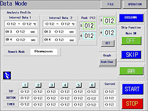
Creation of a Profile Data
MS7000IR has a function to monitor profile data. The
red frames can change the indication of the measurement curve and the
indication of analysis data. It changes with a GRAPH switch.
This function is also in M mode also by AP mode. It
can be trace for 4 colors, 2CH are for controller, and other 2CH are for
measurement.
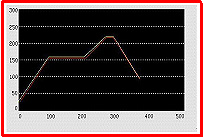
The screen for Creating a profile
The setup data can be saved at each mode. AP mode
data is maximum of 100 files, and M mode is maximum of 100 files.
The data is managed by the Windows Excel CSV files.
The data can be send to the PC, by the CF memory-card. The data can be
analyse with the original software by the Excel on the PC. And the data
can be print-out to A4 size paper by the PC with the original format.
Z axis sem-auto
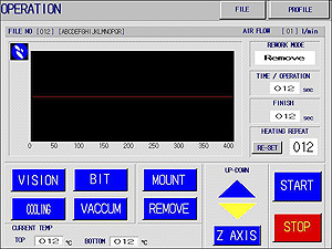
Z axis semi-auto operation screen.
Z axis of MS7000IR is by semi-auto motor controlled. The axis is able to
automatically up and down by the up-down switch. And the last fine
adjust is by manual. Therefore, operation is easy and safety.
Adjustment of the Heating Range
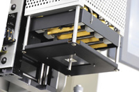
Top Heat Range Adjustor
The heart range of the top heater can be adjust by
the shutter to the head. The shutter is changeable. They are possible to
change by 10mm to 50mm square.
Vision System
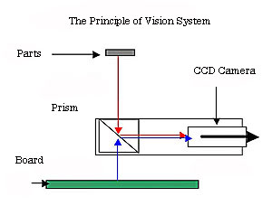
Optical image equality System
The positioning system is by optical image equality.
It is the system that it displays the land image of the board and the
pattern image of the part on the monitor at equal magnification. If
those images fit, it will be the completion of positioning. The sample
below images are 6x8mm CSP.
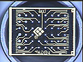
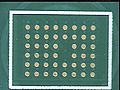
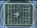
Parts image+board image+both of images.
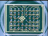
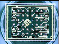
Both of image + adjust = Completion
positioning.
Specifications
| Item |
Specification |
| Component size |
3.0 x 3.0 ---35
x 35mm |
| Board Size |
50 x 50 ---200
x 250mm max |
| Fine Adjust for Rotation |
±5 degrees max
by Z axis by manual |
| Fine Adjuster X and Y |
±5.0mm max by
XY Table by manual |
| Board Thickness |
2.0mm /1Kg Max
|
| Clearance of under the
Board |
25mm Max |
| Clearance of the board Top |
45mm Max |
| Z Axis |
motor control |
| Under support for the board |
by 4 pins on 2
railes |
| Heater Control
System(PID) |
AP |
ITTS
Auto-Profile x 2 |
| M |
Manual 6 zones |
| Parts Pick Up |
Manual pic-up
by Vacuum Bit. |
| Parts replace |
semi-automatic |
| Controller |
Touched Panel
10.4inch Color with Logic controller |
| Top heater |
800VA Middle IR |
| Area
Range:10x10 -- 50x50mm by XY Shutter |
| Bottom Heater |
1.0KVA Far IR |
| Control Data
Save |
AP mode:100
files max |
| M mode: 100
files max |
| Control Data Memory |
Excel CSV file
in the CF Memory |
| Temperature Measuring |
CA-K:
2(controller)+2CH(measuring)
|
| Data Analyzer |
Peak Temp x 4 /
Time-Interval x 2 x 4 |
| Data Graph |
4CH max |
| Monitor |
640x480 dot
10.4 inch (Ext by RGB) |
| Vision System |
AF 70x max with
splitter system |
| Power |
200--240V 2.0
KVA |
| Dimension |
580W x 730D x
750Hmm 60Kg approx. |
| Air |
0.5Mpa Dry
|
The specification are subject to change without notice.