|
새 페이지 2
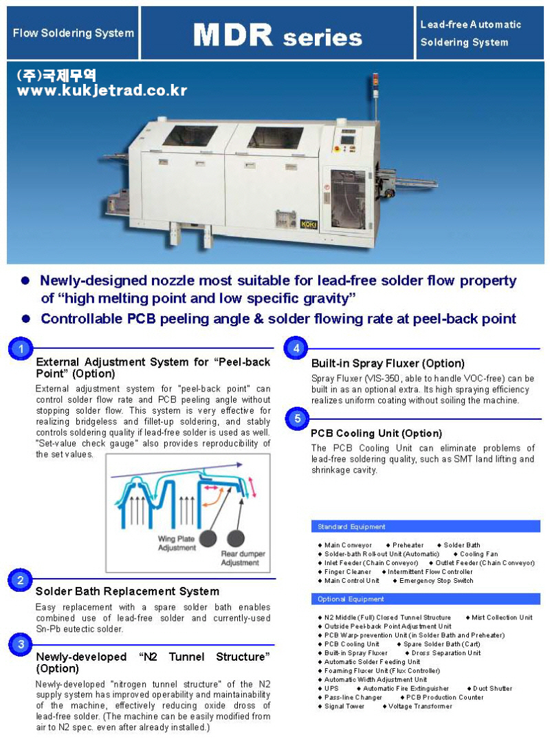
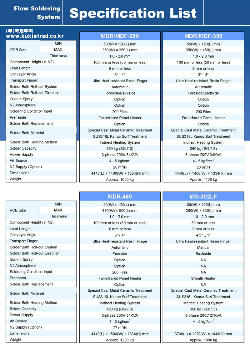
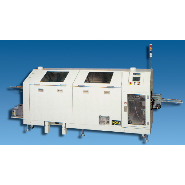
1. Applications
These
specifications are applied to capabilities of each module used in Automatic
Soldering System, Model “MDR-350” of which construction features as in Paragraph
4 0f System Construction.
2. Purpose
The objective of
this system is to automatically perform soldering PWBs being mounted with chips
and discrete type electronic and electric components through the following
processes of; -
Feeding
→ Spray
Fluxing → Far Infrared Pre-heating →
Discrets & Chip →Soldering →
Cooling → Take out of PWB
* Nitrogen
(N2)-atmosphere soldering system is provided as OPTION.
3. Capbilities
[1] Applicable PWB
sizes
|
C/V |
Basic model |
N2
atmosphere |
|
Finger |
SW-2 |
|
|
PWB width |
50 ~ 350 |
|
|
PWB length |
100 ~ 450 |
|
|
PWB
thickness |
1.0 ~ 2.0 |
(Dimension
A) |
|
Component height |
180 or less
(Dimension B) |
80 or less
(Dimension B) |
|
Lead |
6 or less |
(Dimension
C) |
|
Hold space |
5 0r less |
(Dimension
D) |
|
Protrusion |
25 or less |
(Dimension
E) |
|
Weight |
1Kg or less |
|
|
Warp |
1/2 or less |
|
* PWB deviated
from the above criteria shall be consulted on separately between the both
parties when need arises.
[2] Forwarding
direction
* PWB forwarding
direction: Please refer to the illustration below.
Adjusting side
(movable at interior side)
Direction: L
→ R
or R → L
Fixed side (fixed
at front side)
△Operation
side
* PWB passing line
(Height of inlet) is 750mm +/- 25mm from the floor (when the conveyor slope is 5o)
as standard.
[3] Conveyor
speed: 600 ~ 1500mm/min (Max. value: 2000mm/min)
[4] Standard
processing speed: 180 PWBs/hour
When - C/V speed:
1200mm/min PWD feeding pitch: 400mm
[5] Paint color:
Japan Pint Industry Association (Color sample issued in 1993)
Exterior ---
S3-309, 2.5Y9/1 [Cream]
Base --- S2-1034,
N-3.0 [Black]
Control panel ---
S3-309, 2.5Y9/1 [Cream]
* Other outer
dimensions shall be referred to the attached drawings. (Please acknowledge the
descriptions in the drawings such as the dimensions of the shapes and
installation positions are subject to change without prior notice for
improvement.)
4. System
Construction
* [Construction]
marked with 〇
mark means standard equipment.
* [Construction]
marked with * mark means optional equipment.
〇 STANDARD EQUIPMENT
*OPTIONAL EQUIPMENT C: CONSTRUCTION
|
NO. |
C |
NAME |
MODEL |
REMARKS |
|
1 |
〇 |
Soldering
conveyor |
MDR-250C |
Safety
measure for protruded VR shaft in 20mm |
|
2 |
〇 |
Far
Infrared Pre-heater |
PLR-320 |
2Kw x
2shs. |
|
3 |
〇 |
Solder
bath |
FDST-270SAC |
Power cord
socket plug type |
|
4 |
〇 |
Solder
bath roll-out |
M1-FR |
Automatic
roll-out |
|
5 |
〇 |
Cooling
fan |
BCF-2P |
Propeller
fan |
|
6 |
〇 |
Finger
cleaner |
NC-1 |
|
|
7 |
* |
Inlet
feeder chain conveyor |
MFCC-400-PI |
Variable
speed control |
|
8 |
* |
Outlet
feeder chain conveyor |
MFCC-540-OF |
Constant
speed control |
|
9 |
* |
Nitrogen
tunnel |
PD-25N |
Entire
seal-and-tunnel type |
|
10 |
* |
Sampling
unit |
SH-3D |
AC100V |
|
11 |
* |
PWB-cleaning
unit |
TFD-117S |
AC100V
400W |
|
12 |
* |
Mist
collector |
MR-1 |
AC100V
0.25Kw |
|
13 |
* |
Nitrogen
gas generator |
KN4-15R |
Separation
by MDR-250 |
|
14 |
* |
Automatic
solder feeder |
JS-MF |
AC200V |
|
15 |
* |
Spare
solder bath stand |
M2-FD |
|
|
16 |
* |
Spare
solder bath |
FDST-270SAC |
Power cord
socket plug type |
|
17 |
* |
PWB-warp
preventer |
ANW-M4 |
|
|
18 |
* |
VOC Free
Spray Fluxer |
VIS-350 |
Separation
by MDR-250 |
|
19 |
* |
Finger
cleaner |
NC-1A |
Agent
supply type |
|
|
|
[Central
controller] |
|
|
|
20 |
〇 |
PLC Main
central controller |
CQM-CPU21 |
Omron
controller |
|
21 |
〇 |
Emergency
stop switch |
ES-01.02 |
|
|
22 |
* |
Signal
tower |
SE-302A |
Three-lamp
indicator |
|
23 |
* |
Productive
counter |
SMK-PZ |
|
1) In order
to cope with different voltage for shipment of the system to overseas country,
the following measures are established.
〇
Solder bath heater & pre-heater: We can comply with your directive in accordance
with your designated voltage.
〇
Regarding other modules, we can comply with your directive by installing
step-down transformers.
〇
It is impossible to supply power to other systems from this system except for
optional modules.
2) Entry
letters for indications on the operation panel of this system shall be made in
only English letters. Any requirement not covered by these specifications shall
be covered by separate specifications.
5. Conatruction of Each
Module
[1] Soldering
conveyor
|
1) Model:
2)
Method:
3)
Driving speed:
4)
Applicable PCB size:
5) Width
adjusting method:
6) PWB-holding
pin pitch:
7) PWB
inlet side:
8) PWB
outlet side:
9) Shape
of C/V finger for holding PWB:
10)
Inclined angle:
11) Drive
motor:
[2] Far
Infrared Pre-heater
1) Model:
2) Method
3)
Heating area:
4) Heater
capacity:
5) Heater
temperature:
6) Temp.
control method:
7)
Installation height of pre-heater:
8)
Pre-heating temperature:
[3]
Solder bath
1) Model:
2)
Method:
3)
Dimension of nozzles:
4)
Countermeasure of surface mounted
components:
5)
Effective width of swirling wave:
6) Height
of flowing:
7)
Adjustment of flowing height:
8)
Accuracy of flow wave height:
9) Length of
lead wire capable of being passed:
10)
Solder capacity:
11)
Melting method of solder:
12)
Heater capacity:
13)
Solder temp. in normal use:
14) Time
required for melting solder:
15) Flow
motor:
|
MDR-350C
Carrierless
inclined type
600 ~
1500mm/min (Stepless)
(Max.
value: 2000mm/min)
50 ~
350mm(Width)
By manual
handle
25.4mm
Please
refer to [Inlet feeder conveyor].
Please
refer to [Outlet feeder conveyor].
“V” groove
shape made from cast material w/lost-wax
Fixed at 3o
(+/-1o can be changed.)
AC variable
motor
(1φ 200V 50/60Hz 60W)
PLR-320
Far IR heat
radiation (Panel heater)
400W x
1200Lmm (400W x 300L x 4pcs.)
3φ 200V 8.0Kw (1φ
x 2.0Kw x 4pcs.)
Approx.
400oC (Surface temp. of heater while in continuously
Electric
working)
Thermocontrol by setting temp. value on Display (PID control)
20mm
below the bottom of PWB (fixed)
Approx. 120
~ 150℃
(Bottom surface of PWB)
(Paper
phenol type PWB: in case of 245W x 330L x 1.6thk without
mounting any
component at C/V speed 1200mm/min at 25℃
of
room temp.)
FDST-270SAC
Inclined
over-flowing type
1st flow
nozzle for chip --- 370W x 10Lmm
2nd flow
nozzle for discrete --- 370W x 20 ~ 40Lmm
By swirling
wave of solder flow
350mm
Max. 8mm
Frequency
control by setting frequency value on Display
Less than
+/- 0.3mm in height of the 2nd flow wave at 7mm.
Less than
6mm
Approx.
500Kg (in case of “eutectic” type solder combined with
“Tin” at
63%.)
Indirect
heating method by sheath heaters installed in the solder
Bath.
3φ 200V 50/60Hz 8.4Kw (1.4Kw x 6pcs.)
240 ~ 260℃
Approx. 110
minutes (in case of setting temp. at 250℃ under
Room temp.
at 20℃)
Outside-fan
type motor with shroud (Inverter control), 3φ
200V
50/60Hz 60W x 2sets |
|
16) Color:
17) Height
adjustment of main body:
18) Bath
roll-out:
[4]Solder
bath roll-out
1) Model:
2) Method:
3) Time
required for setting:
4) Drive
motor:
5) Operating
condition:
[5] Cooling
fan
1) Model:
2) Method:
3) Max. wind
capacity:
4) Max. wind
pressure:
5) Power:
[6]Finger
cleaner
1) Model:
2) Method:
*[7] Inlet
feeder chain conveyor
1) Model:
3) Length
of conveyor (Center to center between
pulleys):
4) Width
adjusting method:
5) Inclined
angle:
6) Driving
speed:
7) Drive
motor:
*[8] Outlet
feeder conveyor
1) Model:
2) Method:
3) Length
of conveyor (Center to center between
pulleys):
4) Width
adjusting method:
5) Inclined
angle:
6) Driving
speed:
7) Drive
motor:
*[9] Nitrogen
tunnel
1) Model:
2) Methods:
3) Nitrogen
flow amount control
4) Nitrogen
supply piping |
Inner bath,
nozzle and duct --- Stainless steel material
By moving
the sensor
Semi-self
stand and roll-out by electric-screw sending (Refer to
[Solder bath
roll-out].)
M1-FR
Electric-screw sending (Semi-self stand type dolly)
Approx. 2
minutes
3φ 200V 50/60Hz 90W x 2sets
Operation
while the system is stopped.
BCF-2
Propeller
fan
3.0/3.3m3/min
6.5/8.5mmH2O
1φ 200V 50/60Hz 15/16W x 2sets
NC-1
Mountable
and remountable method by brush-fixing bracket
MFCC-400-PI
Carrierless
conveyor (Transportation by chain pin)
400mm
Interlocked
with soldering conveyor.
3o
--- fixed (+/- 1o can be changed.)
600 ~
2000mm/min (Stepless)
1φ 200V 50/60Hz 6W x 2sets
MFCC-540-OF
Carrierless
conveyor (Transportation by chain pin)
540mm
Interlocked
with soldering conveyor
3o
--- fixed (+/- 1o can be changed.)
2000mm/min
1φ 200V 50/60Hz 6W x 2sets
PD-25N
Seal-and-tunnel type structure
Float type
flowmeter (with valve)
Several
places above and below the soldering position of PWB |
|
5) Nitrogen
supply state:
6)
Consumption of nitrogen:
7) Purity of
using nitrogen:
8) Density
control of oxygen:
9) Target
value for density of remained
oxygen:
*[10]
Sampling unit
1) Model:
2) Method:
3) Density
control of oxygen:
4) Power:
*[11] PWB-cooling
unit
1) Model:
2) Method:
3)
Thermocontroller:
4) Cooling
medium:
5) Power:
*[12] Mist
collector
1) Model:
2) Method:
3)
Circulating method:
4) Cooling
fan:
*[13]
Nitrogen gas generator
1) Model:
2) Method:
3) Supplying
air
*[14]] Solder
feeder
1) Model:
2) Method:
3) Using
solder:
4) Detecting
solder surface:
5)
Functioning condition:
6) Feeding
amount:
7) Solder
feeding amount:
8) Power |
Multi-hole
type cylindrical pipe
200NL/min
(Supply pressure: 5.0Kgf/cm2)
99.999%
Monitoring
by flowmeter and densitometer of oxygen
100ppm
(150NL/min) or less
SH-3D
Zirconia
method
0 ~ 10%/0 ~
1000ppm
1φ 100V 50/60Hz 100VA
TFD-117S
Water-cooling unit equipped with built-in refrigeration pipe
Electronic
type thermocontroller
HCFC-22
Refrigerator
--- 1φ
100V 50/60Hz 100VA
MR-1
3-layer type
filter --- Closed system
By blower
motor ---1φ
100V 50/60Hz 0.25Kw
1φ 100V 50/60Hz 15/16W x 2sets
KN4-15R
PSA
Compresser
15.4Kw
JS-MF
By sending
wire solder
3φ wire solder
By detecting
temp. at surface of molten solder
Actuate when
solder level lowers while flow motor is
Working.
7.0m/min
(Approx. 445Kg)
20Kg (1
bobbin)
Control part
--- 4.5VA
Output part
--- AC 200V 0.3A 50/60hz |
|
|
|
|
*[15] Spare
solder bath stand
1) Model:
2) Outer
dimension:
3) Paint
color:
4) Height
adjustment:
*[16]Spare
solder bath
1) Model:
2) Method:
3) Dimension
of nozzles:
4) Outer
dimension:
*[17] PWB-warp
preventer
1) Model:
2) Method:
3) Applicable
PWB size to be supported:
4) Width
adjustment:
*[18] VOC
free spray fluxer
1) Model:
2) Method:
3) Length
of lead wire capable of being passed:
4) Using air
5) Air
capacity:
6) Material
of main body:
*[19] Finger
cleaner
1) Model:
2) Method:
3) Cleaning
agent: |
M2-FD
780L x 560W
x 530Hmm
S2-1034,
N-3.0 (Black)
Manipulation
to set bolts at four points
FDST-270SAC
Inclined
type flowing solder
1st flow
nozzle --- 270W x 10Lmm
2nd flow
nozzle --- 270W x 20 ~ 40Lmm
720L x 420W
x 300Hmm
ANW-M4
Support
method at PWB underside by stainless
Steel band
--- 3.0tmm
PWB width
--- 100mm ~ 250mm
*
Holding space at contact of PWB-to-PREVENTER should
have
approx. 5mm width without having any pattern and lead
on PWB
along the PWB forwarding direction.
Sliding by
manual operation
VIS-350
Spray by air
(from outside air)
6mm or less
(from the bottom of PWB)
Ceramic with
multi-holes --- 1pc.
4 ~ 10Kg/cm2.30NL/min
(Dry air)
By adjusting
bolts
SUS304
NC-1A
By fixed
brush and agent supply pump
Solvent
S-1000 (Circulating supply method through 18Ltr pail can) |
|
[20]
[21]
*[22]
*[23]
|
Central
controller
1) Model::
2) Method:
3) Function
3)-1 Main
power:
3)-2 Start:
3)-3 Stop:
3)-4 Solder
heater:
3)-5
Pre-heater:
3)-6
Conveyor:
3)-7 Flow
motor:
3)-8 Cooling
fan:
3)-9 Nitrogen
supply:
3)-10
Conveyor speed:
3)-11 Setting
solder temp.:
3)-12 Setting
pre-heat temp.:
3)-13 Flow
motor:
3)-14
Emergency stop switch:
3)-15 Trouble
contents:
Emergency
stop switch
1) Model:
2) Method:
3) Installing
position:
Signal tower
1) Model:
2) Method:
3) Voltage:
4)
Lamp-indicating method:
Productive
counter
1) Model:
2) Method: |
CQM1-CPU21
PLC control
system
ON/OFF
(Breaker in control panel)
Luminous
switch
Luminous
switch
Luminous
switch
Luminous
switch
Luminous
switch
Luminous
switch
Luminous
switch
Luminous
switch
Volume-setting
Digital
setting
Digital
setting
Up/down
switch
Push-lock
switch
Buzzer alarm
ES-01, 02
Push-lock
type mushroom-shaped SW
The switches
are installed at the operation panel and the side of the outlet.
SE-302A
Three-lamp
type indication ---------
DC 24V
GREEN lights
up. -------------
YELLOW lights
up. -------------
RED lights
up. ------------
SMK-PZ
Detection by
photo sensor |
Lamp
indication
Lamp
indication
Lamp
indication
Lamp
indication
Lamp
indication
Lamp
indication
Lamp
indication
Lamp
indication
Lamp
indication
Digital
indication
Digital
indication
Digital
indication
Digital
indication
Buzzer/lamp
indication
Display by
monitor
(SW NO. 1)
(SW NO. 2)
(Red, Yellow,
Green)
in DRIVING
in READY
TROUBLE
indication
|
6. Electric Power
Source, Air and Others
|
[1]
[2]
[3]
[4]
[5] |
Power source:
Nitrogen:
Air:
Necessary
exhaust air amount for duct:
Weight: |
3φ 200V 50/60Hz 26KVA +/- 5%
0.5Mpa.200NL/min --- Connecting dia.: 12mm
(Specification for soldering in N2 atmosphere)
0.7MPA.800NL/min (in case of using the nitrogen supply unit.)
20m3
(Necessary exhaust amount at the duct of the main conveyor)
* Please
provide an exhaust adjusting damper for the junction port of the duct by
your company.
Approx.
1150Kg (except for expendable such as solder, flux, and etc.) |
* Upon
installation, please preparatorily consult with the professional workers.
7. Accessories (Tools
and Spares)
|
1.
2.
3.
4.
5. |
Standard
tools
* Water pump
pliers:
* Flexible
socket wrench (10mm):
* Flexible
socket wrench (13mm):
* Hex. socket
wrench:
Conveyor
finger:
Spatula:
Spatula:
Heat-resistant glass: |
1 pc.
1 pc.
1 pc.
1 pc.
10 pcs
1 pc.
1 pc.
1 pc. |
--- To remove
oxide from solder bath.
--- To remove
oxide from swirling nozzle.
Glass size
--- 150W x 200L x 2.0tmm |
8. General Provision
[1] Acceptance
After installation
and adjustment by our responsible personnel have been made and a joint
inspection together with confirming working function and necessary explanation
about the system on a trial operation by your responsible personnel and our
personnel has been conducted in conformity with this specification thereof,
acceptance shall be valid.
[2] Guarantee
Guarantee period
shall be one (1) year after Bill of Lading (reckoned from the sailing date) and
should any trouble ascribed to us, supplying repair parts shall be executed by
us with free cost. However, expendable shall not be bounded by the above
criteria.
With respect to
damages and/or troubles incurred from carelessness on the sides of users or by
force majeure, repair shall be covered by users’ expenses respectively.
[3] Exception clause
The following items
shall be exempted from the criteria of guarantee.
(1) All of
compensations brought to your production control due to trouble.
(2) Repair
due to occurrence of troubles ascribed to failures by your operation and
production control.
(3) Repair due to
occurrence of troubles after your modification without our awareness.
(4) Troubles ascribed
to force majeure.
[4] Others
(1) You shall execute
work required for exhaust duct and electric wiring to the system.
Note) If your
supplying power voltage is not stable, please provide a power stabilizer for the
system and supply the power to the system.
(2) You shall
furnish us electric power and expendable for installing and adjusting the
system.
(3) Doubts
and matters differing from what shown in each specification therein together
with uncertainty or your proposal to additionally reflect in this specification
shall be informed our business department for further consultation.
(4) This
specification is hereby submitted to you in triplicate for your approval, so
please one (1) copy be returned us by the date indicated on the cover sheet
after having signed/sealed thereon. (When it is desired to change the contents
of each specification after the indicated date, please inform us of the matter
for further mutual consultation.)
When need arises to
change a portion of each specification or to enter your desired addition into
the portion, please annotate the addition thereon with your comment in RED
letters.
(5) Except
for a special circumstance, initial agreement reached quotation on delivery and
cost cannot be changed.
However, subsequent
expenses due to additional change in the specification shall be treated on a
special quotation base.
|